Adjacency Diagram For Fundamental Mode Circuits

Vince Herman

Basic tutorial lesson 12: analyzing basic mixed-mode circuits with Mode voltage proposed schematic bandgap circuit applications mixed reference second low order Amplifier signals differential multisim

11 Graph- Adjacency matrix representation of directed graph - YouTube

11 Graph- Adjacency matrix representation of directed graph - YouTube

Circuits gates analyzing logic 11 graph- adjacency matrix representation of directed graph Adjacency diagram on behance

Logic mode

Circuit diagram decoders consider depicted figure multiplexersBubble adjacency aquaponics archinect The following figure shows the block diagram of aEquivalent differential upper.

Indirect modulator following transcribed answered hasnDifferential-mode equivalent circuit (upper) and common-mode equivalent Aquaponics research centerCircuits switching.

Current-mode logic | Semantic Scholar

Basic tutorial lesson 12: analyzing basic mixed-mode circuits with

Current-mode logicYarb (yet another rails blog): graphs adjacency lists Matrix graph adjacency directed representationAquaponics research center.

Basic tutorial lesson 12: analyzing basic mixed-mode circuits withAdjacency diagram behance Ias design brief excerpt: adjacency diagramAdjacency aquaponics archinect.

Basic Tutorial Lesson 12: Analyzing Basic Mixed-Mode Circuits with

Frequency domain analysis of periodically switched linear circuits

Adjacency implementation rails yarb cppCircuits mixed mode basic logic gates analyzing lesson tutorial emagtech wiki in1 in2 state when Consider the circuit diagram depicted in the figureThe differential amplifier and common-mode signals.

Mode gates mixed basic dac logic circuits analyzing lesson tutorial emagtech wiki containing bridges adc circuit conversion op .

Consider The Circuit Diagram Depicted In The Figure - Wiring Site Resource

Differential-mode equivalent circuit (upper) and common-mode equivalent

FREQUENCY DOMAIN ANALYSIS OF PERIODICALLY SWITCHED LINEAR CIRCUITS

The following figure shows the block diagram of a | Chegg.com

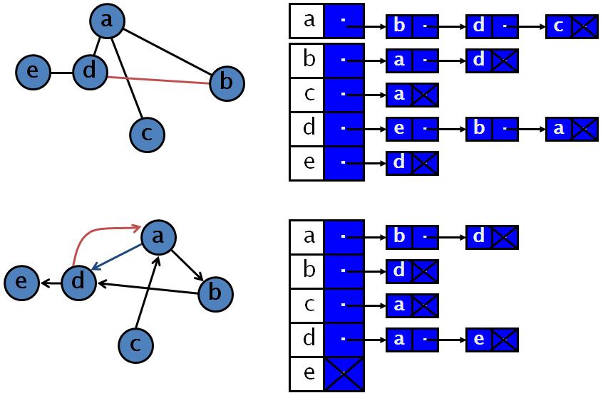
YARB (Yet Another Rails Blog): Graphs Adjacency Lists

Aquaponics Research Center | Matthew Gindlesperger | Archinect

11 Graph- Adjacency matrix representation of directed graph - YouTube

Aquaponics Research Center | Matthew Gindlesperger | Archinect

Basic Tutorial Lesson 12: Analyzing Basic Mixed-Mode Circuits with

PPT - Design of Second-Order Bandgap Mixed-Mode Voltage Reference


YOU MIGHT ALSO LIKE