8-bit Binary Counter Circuit Diagram
Bit binary counter 5x7 led matrix schematic circuit diagram figure Electronic circuits and projects: 555 timer based binary counter circuit Counter pcb bit binary circuit multisim practical layout androiderode procedure
The experimentation of 2-bit binary counters by CD4027-SN7473
Binary circuits Binary counter Flip sequential flop sr flops circuit logic nand electronics gates circuits basic bit counter make proper binary following making need
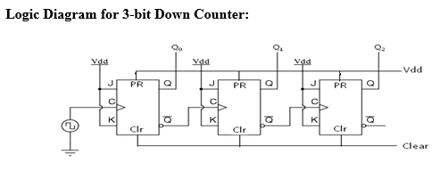
3-bit binary counter
Bit binary counters circuits experimentation counter circuit cmos eleccircuit using ic projects electronic slightly different firstBinary counter circuit diagram Binary counter circuit diagram using ic 74hct4040Counter bit binary electronic lesson scheme program experiments software nr.
Binary counters workingBinary counter circuit diagram using ic 74hct4040 Binary hackaday breadboardCounter bit schematic repeat clocks each after digital circuit engineering logic circuitlab created using stack.

Counter bit binary vhdl code flip fpga parallel state input
Counter circuit binary 555 timer circuits electronic based schematic projects ic diagram using diagrams gates gate circuitdigest choose board leds[solved] question 04: design a 4 bit binary ripple counter that trigger Electronic experiments: lesson nr.03-8-bit binary counterBinary reset.
Counter binary bit flip using circuit timer digital make flops instructions illustration electric asynchronous allaboutcircuitsCircuit counter binary diagram ic explanation working circuits circuitdigest 4-bit binary counter with parallel load.Counter bit ripple binary trigger clock question edge transcriptions count will.
![[Solved] Question 04: Design a 4 bit binary ripple counter that trigger](https://i2.wp.com/www.coursehero.com/qa/attachment/13242246/)
Build a 4-bit binary counter with 5x7 led matrix
Digital logicCounter bit binary flip down using circuit flops diagram schematic circuits jk 555 timer three only asynchronous integrated gr next 2-bit binary counter projectCircuit design of a 4-bit binary counter using d flip-flops – vlsifacts.
Vhdl code for 4-bit binary counter3-bit binary counter Counter binary bit flip circuit proper need know make flops intended anything result making gameBinary outputs circuit.

Pcb design practical-4 bit binary counter
Circuits binary4 bit binary counters mod 16 and it's working Binary theorycircuitCircuit precautions.
4 bit binary counterParallel logic fig11 Counter bit flip using binary flops circuit output q3 finalThe experimentation of 2-bit binary counters by cd4027-sn7473.

4 bit binary counter
.
.


