555 Timer Inverter Circuit Diagram
Voltage inverter using a 555 schematic circuit diagram Inverter 555 circuit timer 220vac 12vdc 12v power inverter using 555 timer
Simple 100W Inverter Circuit with 555 TIMER IRFZ44N - YouTube
555 timer inverter circuit Multisim timer inverter circuit Schematic lab engineering timer pwm diagram
How to make portable inverter with 555 timer ic
Inverter circuit 555 ic ne555 power using circuits wave simplest diagram output single bridge homemade explored square type will projects555 inverter mosfet ne555 frequency eleccircuit circuits sine volts Multisim inverterInverter circuit timer ic electronics lab diagram 220v 12v.
555 inverter timer circuit 12v ic 220v schematic diagramDiy 555 inverter timer circuit Inverter 555 timer circuits6 best ic 555 inverter circuits explored.

Inverter 555 schematic timer circuit mosfet output signal homemade electronoobs circuitos
Inverter circuit diagram using 555 timerInverter circuit voltage diagram schematic using circuits ne555 generator ups power ic 555 inverter timer diy wave circuit schematic square potentiometer adjust output electronoobs circuitosInverter circuit using 555 timer simple 230v diagram ic ne555 battery used npn.
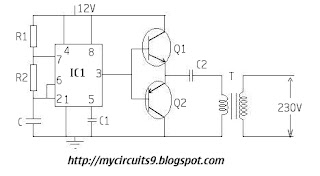
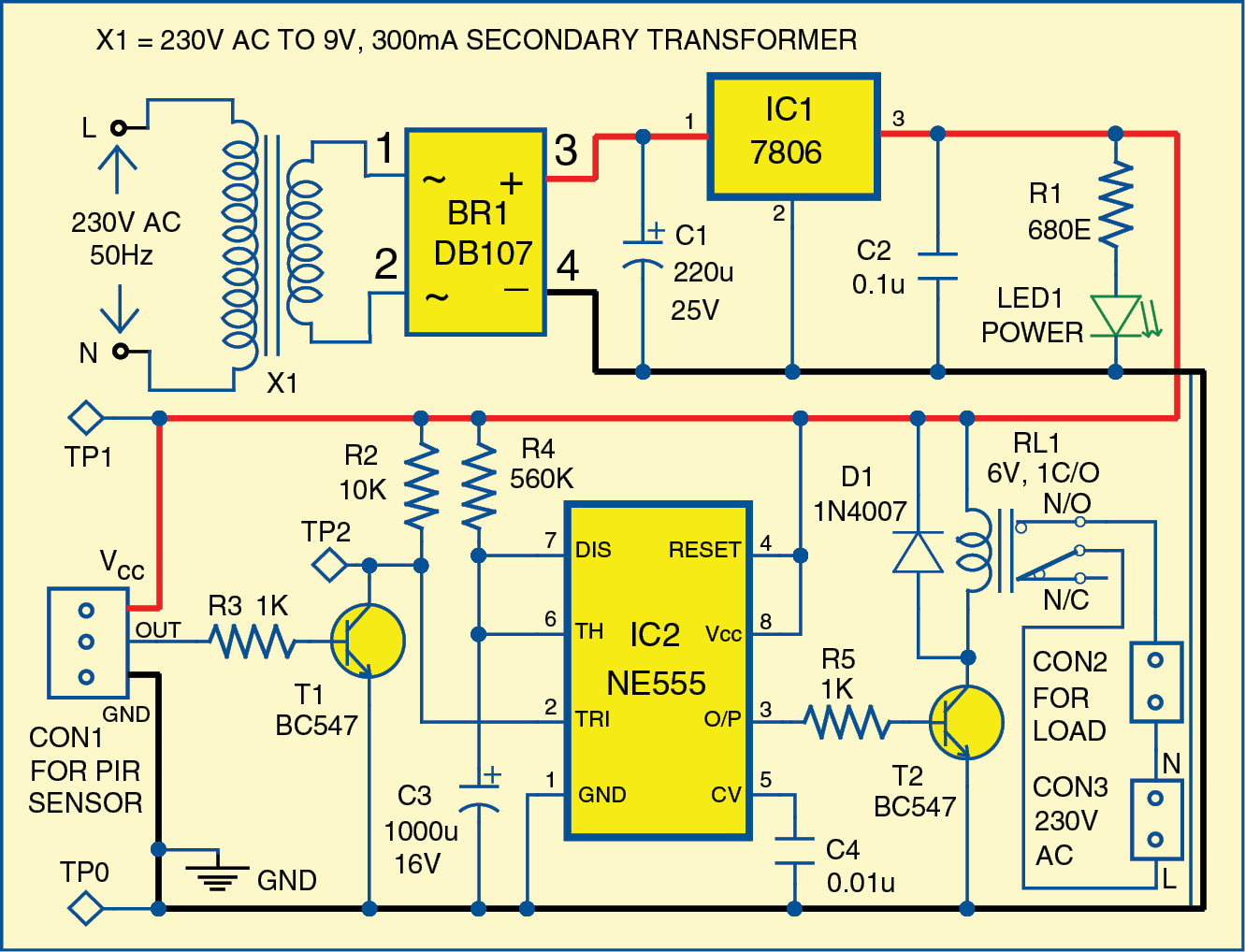
555 timer inverterInverter timer ic transformer Simple motion detector using ne555 timer circuit250w inverter 555 timer (ic1) circuit diagram.

How to make 100w inverter using 555 timer ic
555 timer ic pin diagram features and applicationsUsing 555 timer ic as pwm generator Inverter diagram circuit 250w simple timer circuits ic1 electronic drawing projects electric dc ac getdrawings electrical electronics gr next supplyMy first (working) 555 transformer driver circuit.
Inverter mosfet ne555 volts eleccircuit sine voltage schematics 50hz transformer amplifier inverters figure1555 timer ic inverter circuit schematic 12v to 220v ~ electronics lab Circuit 555 ic inverter pwm circuits simple bridge driver homemade processor generator adjustable sine wave pure spwm functions constitutes whileDiy 555 inverter timer circuit.

Ic 555 inverter circuit using mosfet
555 timer ic inverter 12v to 220v ~ electronics labMotion circuit ne555 detector using timer simple diagram projects electronic electronics circuits fig 6 best ic 555 inverter circuits exploredInverter 100w.
Inverter schematic diy circuit timer final electronoobs circuitos230v simple inverter circuit using 555 timer Inverter power timer circuit 600w diagram schematic explanation555 inverter ic circuit circuits homemade diagram explored astable used dc its projects oscillator wherein implementing function mode standard source.

Irfz44n inverter 100w
555 timer diagram internal ic circuit astable multivibrator monostablePower inverter with 555 timer 555 timer ic astable multivibrator circuit circuits integrated datasheet chips electronic diagram555 timer inverter circuit.
6 best ic 555 inverter circuits exploredPin on electronics projects diy Circuit astable timer transformerDiy 555 inverter timer circuit.

Simple 100w inverter circuit with 555 timer irfz44n
555 timer ic electronic circuit astable multivibrator integrated .
.


